In system-level design, common EOS (Electrical Overstress) testing ports include AC power, telephone lines (RJ11), coaxial cables, and Ethernet ports (RJ45). Since these ports are often routed outdoors, they are more susceptible to EOS and surge events. Therefore, during the safety certification phase of electronic products, EOS/Surge testing is typically conducted on these ports to enhance their resistance against external electrical stress and reduce the likelihood of damage caused by EOS or surges later in the product's lifecycle.
This article focuses on EOS/Surge testing methods for high-speed signal ports such as Ethernet and USB. There are various EOS/Surge testing standards for Ethernet ports, which vary depending on product type or application region, including the IEC 61000-4-5 for IT equipment, GR-1089 for North American telecom, and K.21 for European telecom standards. These standards all specify Common Mode and Differential Mode Surge testing using waveforms of 1.2/50 μs open-circuit voltage and 8/20 μs short-circuit current.
The Common Mode Surge test setup is shown in Figure 1. The testing method involves connecting the signal lines of the Ethernet port (2 differential pairs for 10/100 Mbps, 4 differential pairs for 1000 Mbps) to the High terminal of the surge generator, while the Low terminal is connected to ground. Surge voltage is injected into the signal lines, with each voltage level tested 5 times at 60-second intervals. It’s important to note that each regulation specifies different testing impedances and voltages, so careful verification is needed before testing.
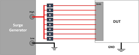
Figure 1: Common Mode Surge Test Setup
The Differential Mode Surge test method differs from the Common Mode. In Differential Mode, surge energy is injected between signal pairs (e.g., TX+ and TX-). The methods vary slightly across standards. This article uses IEC 61000-4-5 and GR-1089 Intra-Building as examples:
•Under IEC 61000-4-5, the test impedance is 42 ohms. The High port of the surge generator connects to 7 Ethernet signal lines, and the Low port to the remaining one. After each test, the Low port is rotated to the next signal line until all 8 lines have been tested — resulting in 8 test combinations. Each test voltage level is injected 5 times, with 60-second intervals. Due to the larger number of combinations, Differential Mode testing takes longer than Common Mode. See Figure 2 for the setup.
•In GR-1089 (Intra-Building), the High port connects to one signal line while the Low port connects to the remaining seven. All 8 signal lines must be connected to the High port in turn. The test impedance is 8 ohms. See Figure 3 for the setup.
Despite minor differences between IEC 61000-4-5 and GR-1089, both aim to validate a product's EOS/Surge robustness to prevent interference-induced failures.

Figure 2: IEC 61000-4-5 Differential Mode Surge Test Setup

Figure 3: GR-1089 Differential Mode Surge Test Setup
In addition to the ports and standards mentioned above, recent years have seen an increase in EOS-related failures of external interfaces in smartphones, computers, and TVs — both during production and after-market usage. To address this, major brands have supplemented the traditional ESD Direct-Pin Injection tests with Low-Voltage EOS Direct-Pin Injection Tests to enhance port robustness.
The waveform also follows the IEC 61000-4-5 1.2/50 μs and 8/20 μs standard, with a 2-ohm series impedance. Since the tested ports are mainly high-speed interfaces like USB and HDMI, the starting voltage, voltage step size, and pass criteria are much lower than those used in Ethernet testing (e.g., a test spec requiring the differential signal pair to withstand EOS at ±25V, with 2V or 5V voltage steps).
This lower voltage allows better sensitivity in evaluating design improvements or adjusting specs. The testing method involves connecting the High terminal of the low-voltage surge generator to the signal line under test and the Low terminal to system ground. The surge energy is injected according to test voltage, interval time, and number of pulses as defined by the brand. See Figure 4 for the test setup.

Figure 4: Low Voltage EOS Test Setup
These three EOS/Surge testing methods can be selected based on the product’s application environment. Though their implementations differ, the ultimate goal is the same — to enhance the EOS tolerance of electronic products. Therefore, it is recommended to consider EOS/Surge protection strategies during the early stages of system design to improve robustness and reduce the risk of product failures caused by EOS during manufacturing or in the field.