Many ports to transferring video data, such as display port, CVBS, HDMI and so on, can be employed on electronic products, where the HDMI interface is most widely applied. It can be observed for the HDMI interface on notebook computers, televisions and set top boxes (STB).
HDMI Licensing Administrator, Inc., (HDMI LA) issued HDMI2.1 in 2017, where the transfer speed of Transition Minimized Differential Signaling (TMDS) for HDMI2.1 not only increased from 18Gbps for HDMI2.0 to 48Gbps but also the resolution that HDMI supports is enhanced from 4K to 8K. In the way to transfer TMDS pairs, HDMI2.0 is comprised by three sets of TMDS Data Pairs (Data0, Data1, Data2) and one set of TMDS Clock Pair (as shown in Figure 1). HDMI2.1, which employs the Fixed Rate Link (FRL) similar to the architecture of DisplayPort, will define four sets of TMDS Data Pairs as Data lane (Lane0, Lane1, Lane2, Lane3) and embed clock inside them. Such architecture can promote the data rate (as shown in Figure 2). In addition, the chip processes for HDMI2.1 are much more advanced than those for HDMI2.0. The tolerance level of ESD will be relatively reduced.
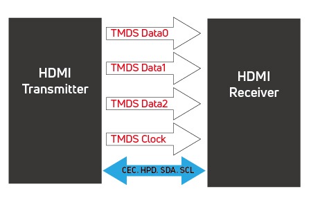
HDMI2.0
TMDS Pair Data-Data2 and Clock
One differential pair is 6Gbps(Max.).
6Gbps x 3 = 18Gbps
Figure 1. Illustration for HDMI2.0 signal channel
-mode_%E5%B7%A5%E4%BD%9C%E5%8D%80%E5%9F%9F-1-md3ay6.jpg)
HDMI 2.1
TMDS Pair is embedding clock(Land0-Land3)
One differential pair is 12Gbps(Max.).
12Gbps x 4 = 48Gbps
Figure 2. HDMI2.1 Fixed Rate Link (FRL) mode
For audio signals, eARC is added to change from the common mode ARC using Pin14 only to differential pairs using Pin14 and Pin19. The data rate will also be increased from 1Mbit/s to 37Mbit/s to provide better sound quality.
During the development and design of electronic products (for example, STB, monitor and notebook computer), in order to prevent the ESD energy produced during plug-in and plug-out at the user end from HDMI failure, many brand companies not only will perform air discharge and contact discharge test on mechanism or interface connector, but also directly make the direct pin injection to signal lines at HDMI port (tested up to 8kV) when verifying ESD (IEC61000-4-2) on product. This will be used to simulate the ESD phenomenon when cable is plugged in or plugged out by users, so that can reduce the field return from the client. In such severe testing condition, however, the chip could not endure. Therefore, an ESD device is needed to add on the HDMI port to prevent this issue and pass ESD test.
For the ESD on HDMI 2.1 port, the AMAZING’s proposal is AZ1123-04F, a four-channel protection device, packaged in DFN2510P10E. Such design is very convenient on PCB routing. The parasitic capacitance of the component is 0.2pF (Typ.). AZ1123-04F can also endure IEC 61000-4-5 Surge (8/20ms) up to 6.5A. For the most important clamping voltage on ESD device, the clamping voltage at 16A (ESD 8kV) is about 10V only from the AZ1123-04F TLP I-V curve in Figure 3.

Figure 3. AZ1123-04F TLP I-V curve
For the protection of HDMI control line (SDL/SDA/HPD/Pin 14), it is recommended AZC199-04S packaged in SOT23-6L be employed. The surge robustness of AZC199-04S is up to 6A of IEC61000-4-5 (8/20ms), where the clamping voltage of ESD at 16A is 11V only (as shown in Figure 4).
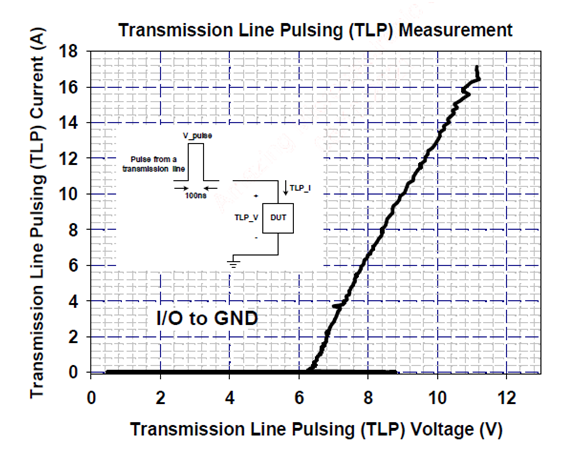
Figure 4. AZC199-04S TLP I-V curve
If CEC signal lines are used, it is recommended AZ5123-01F packaged by DFN1006P2X for protection. The clamping voltage of ESD at 16A is 7V only (as shown in Figure 5). The system can be more efficiently protected with the advent of ESD energy.

Figure 5. AZ5123-01F TLP I-V curve
When developing and designing the system, it is recommended the ESD devices be designed in the circuit to protect on the signal lines. This can avoid the repair issue on the market end. The ESD solution for HDMI2.1 is shown in the figure below.
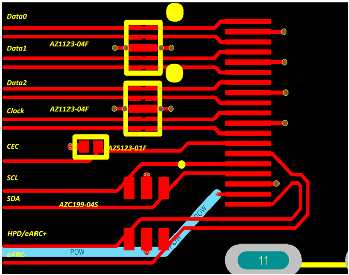
Figure 6. HDMI2.1 ESD solution